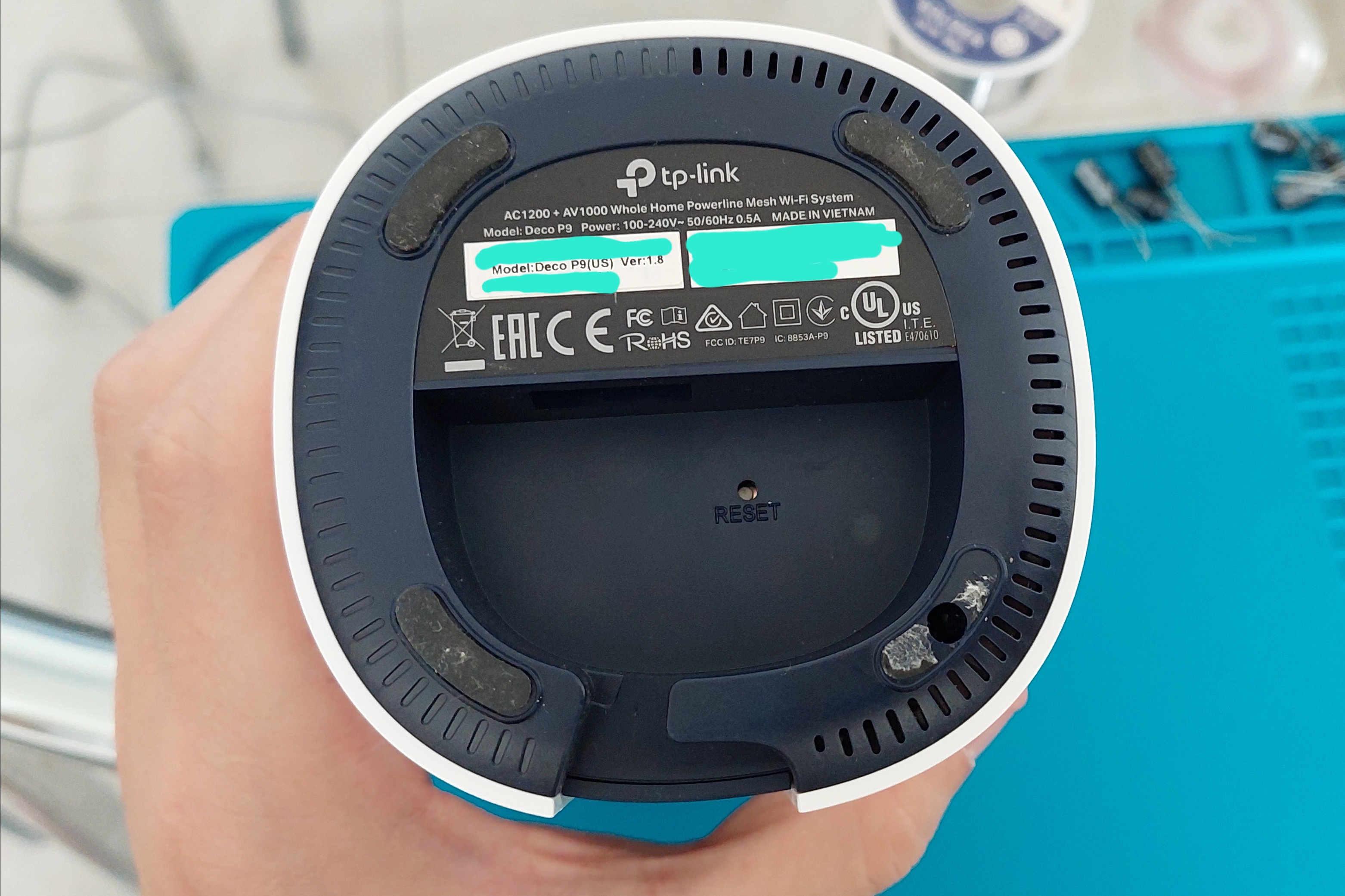
During the pandemic I worked from home like most people. I worked from a corner desk in our bedroom and my team would complain that my wifi would crap out every time I started to talk. After asking around I decided the best solution would be to purchase some mesh network access points to help the wifi stretch from our living room to our bedroom. The ones I settled on were the TP-Link Deco P9. I chose this model because it has both powerline and wifi backhaul, and had a power supply that would accept 220V.
A few months ago they started to emit a high-pitch whine - nearly ultrasound but extremely loud. I put the loudest one in storage and moved them around to minimize the impact of the sound and started looking into why it was happening and how I could fix it. After some research, I found this thread in the TP-Link forums that squarely set the blame on the two 16V 470µF filtering capacitors. It took a few months to order all the equipment I needed, but after fixing them I wanted to share the process (with pictures).
All the equipment I thought I needed
- A silicone mat to do the work on.
- A soldering iron. I got a butane powered one thinking it would be more convenient and free up an electrical socket. It ended up not heating up enough and being extremely finicky to get the solder to flow. The chisel tip developed a notch very quickly - not very confidence inspiring for the long term.
- Fume extractor - this really helped; it was a last minute addition but I’m really glad I got this.
- Solder wick
- Solder
- Flux - I got some cheap flux pens from amazon.
- Screwdriver
- Spudger
- Tweezers
- Some glue - I used some silicone glue we have lying around from the kids’ crafting supplies.
And most importantly - a set of 16V 470µF capacitors to replace the faulty ones.
All the equipment I’ll be ordering now
- A third hand
- A new soldering iron
- A multimeter
- A LCR meter
- A ESR tester
- A component tester
The process itself
- Expose the working area
- Remove the old capacitors
- Place the new capacitors
- Close everything back up
Removing the outer shell and exposing the work area
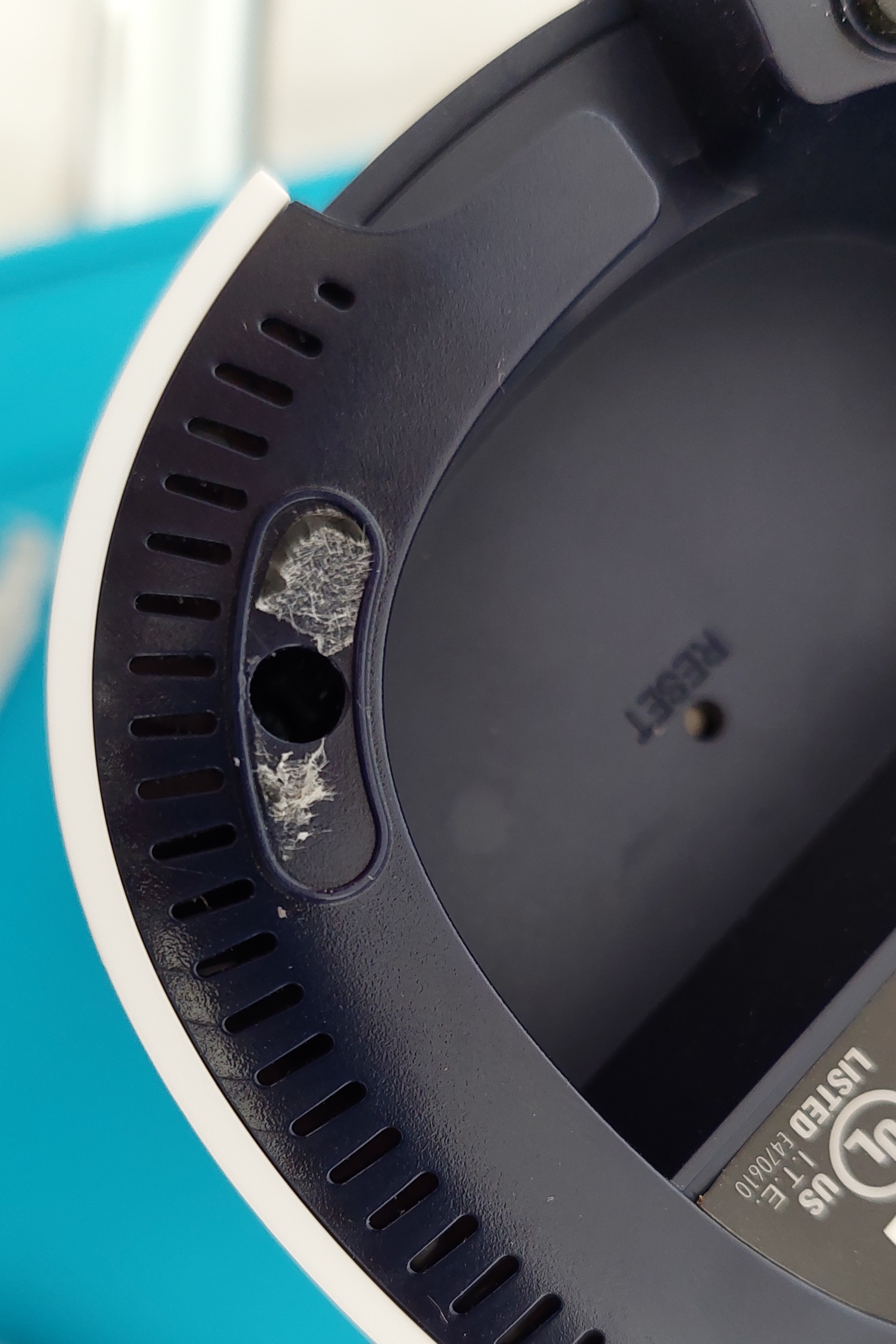
First, remove the feet with the spudger - the adhesive is on a paper backing and will leave around half on the main body. This is ok because we’ll reapply it with some glue at the end, but make sure not to tear the feet themselves.
Next, remove the recessed screws. These are recessed fairly deep in a narrow channel - your screwdriver will need at least 2cm of neck to reach them. Most modular screwdriver kits do not have sufficiently long necks - I was lucky and had exactly what I needed lying around.
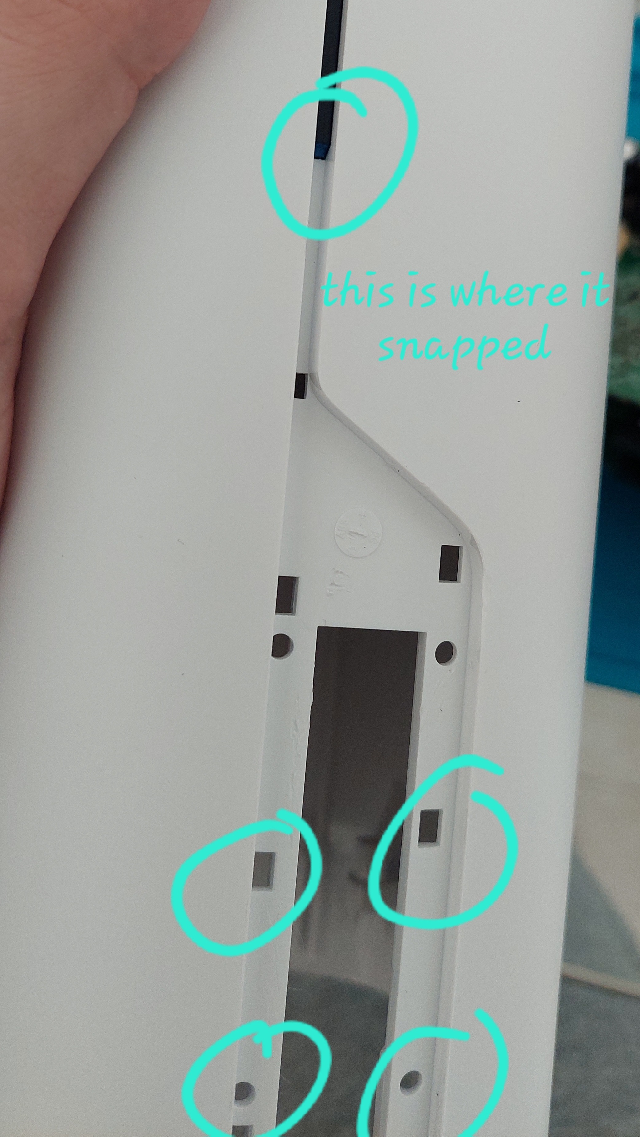
Now spudge the plate covering the network ports. Only lift the bottom few - I snapped the plastic trying to remove the whole thing which was unnecessary.
Finally, grab main part, and give the bottom a good tug - it should start coming out.
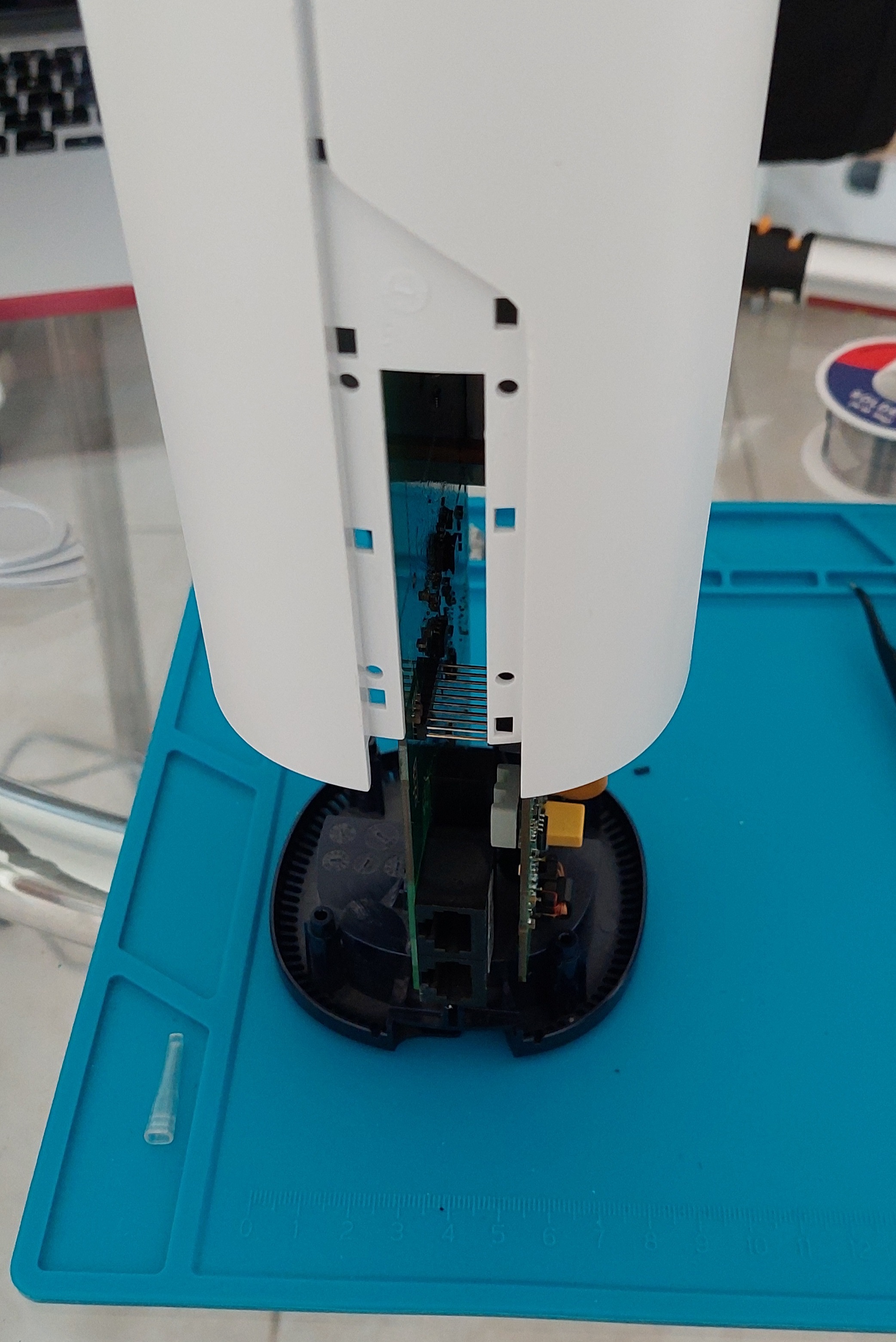
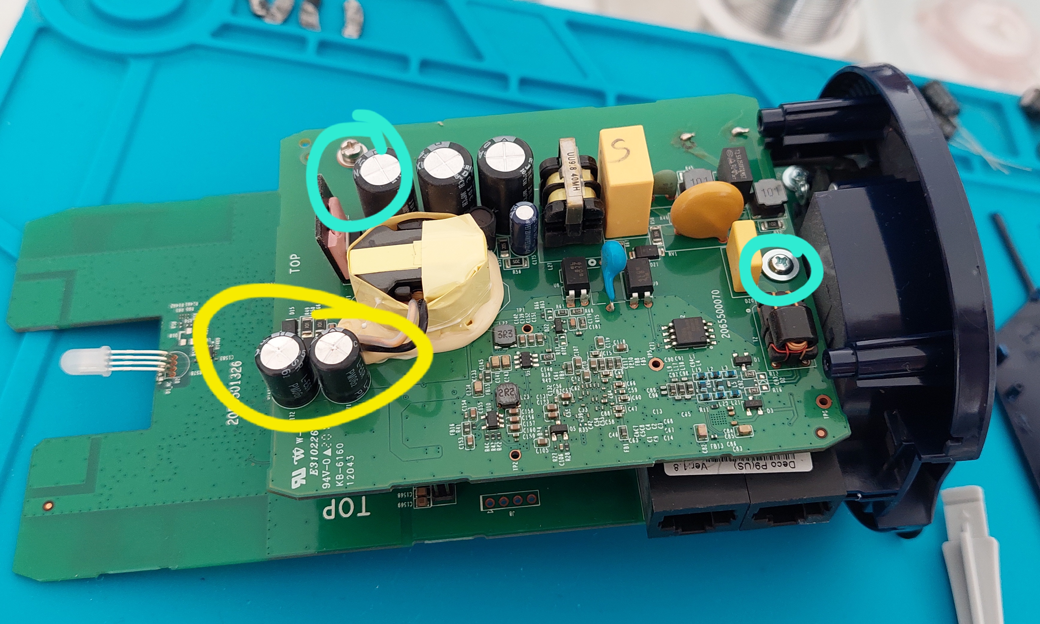
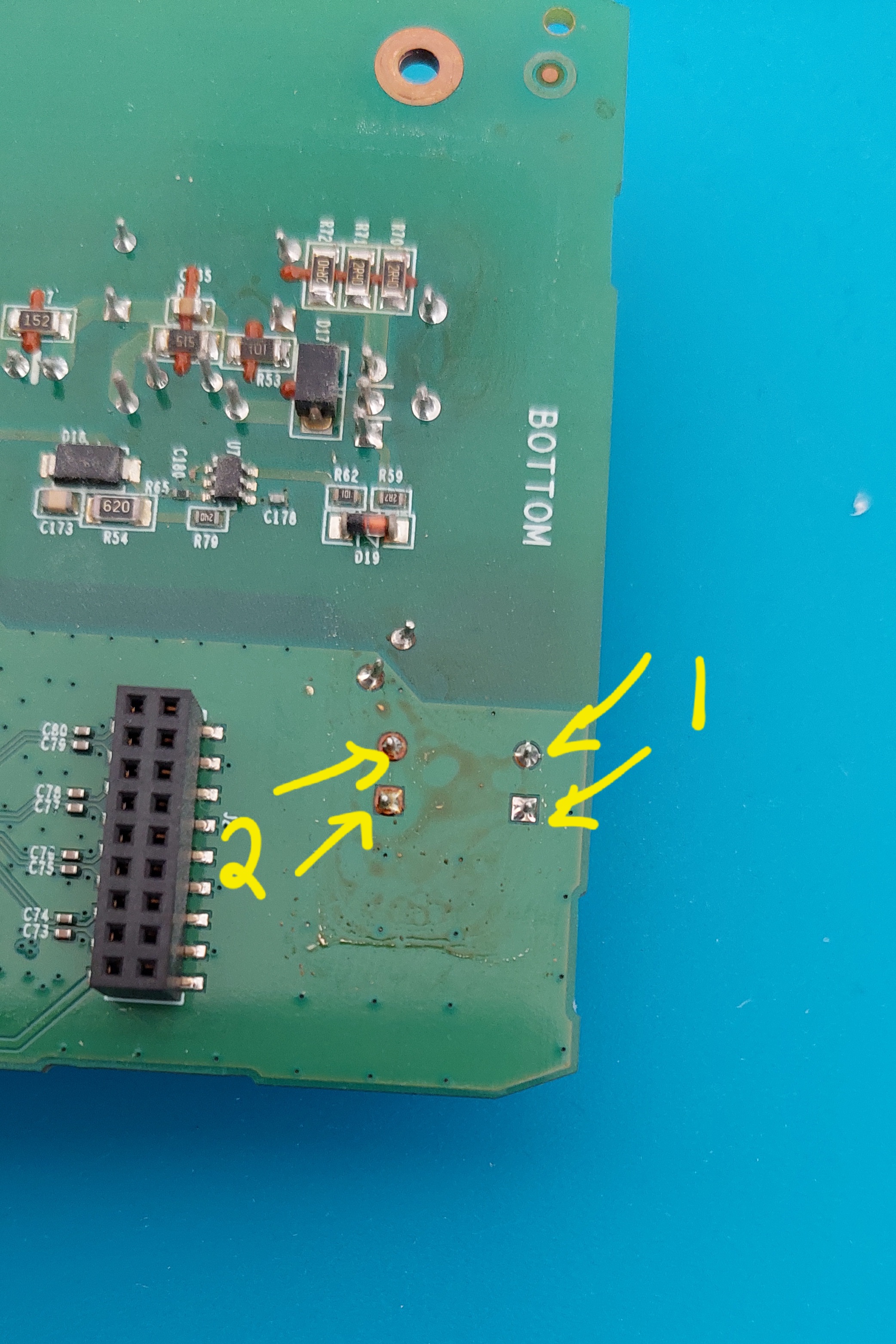
The Deco P9 has two PCBs inside, connected by a grounding pylon and a jumper set. We need to work on both sides of the high-voltage PCB, so we’ll need to remove the two screws and gently apply pressure to disconnect the jumpers.
Removing the capacitors
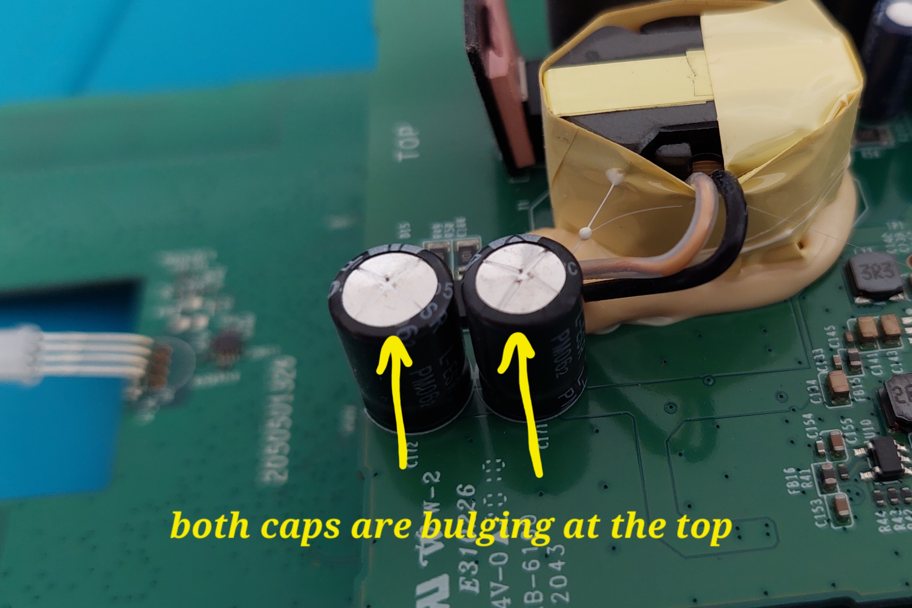
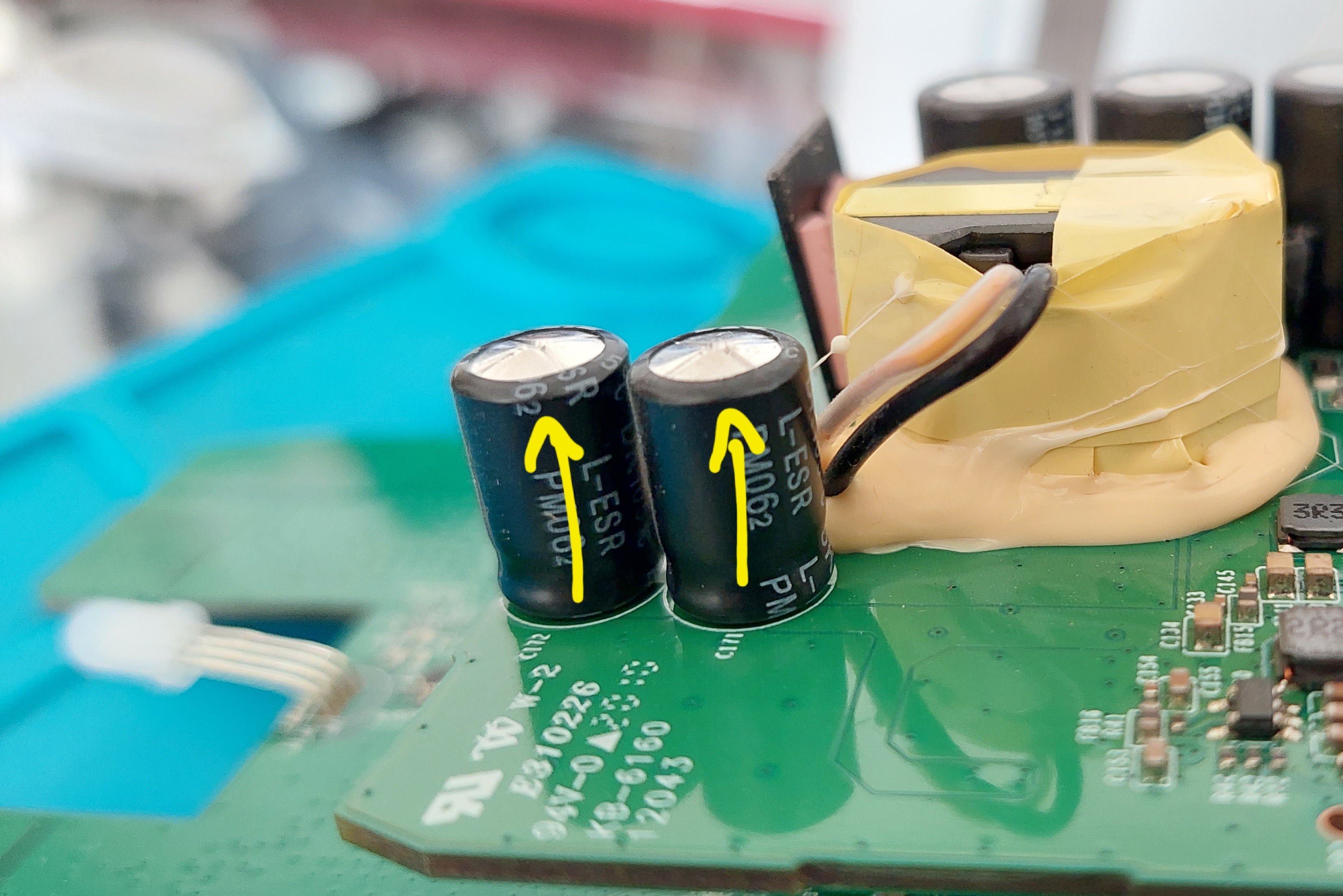
These are the two capacitors that need replacement - see how they’re bulging at the top? That’s a sign that they are failing and need to be replaced.
I had a lot of difficulty removing them from the board - probably a combination of using a cheap soldering iron and the board itself acting as a giant heatsink. I found that grabbing them with pliers and pulling the leads out first was more useful than trying to remove them cleanly.
Clean up the board with some solder wick and flux so it’s obvious what’s going on, and Louis’ your uncle.
Placing the new capacitors
I picked out two 16V 470µF capacitors - trimmed the leads to 1cm and got to work lining them up. I had some difficulty getting them back through the holes, but I suspect that’s more to do with a crappy soldering iron than anything else
Closing everything back up
Place the PCB back in place, tighten the two screws that anchor it, and put the PCB assembly back into the top part. Then put the four screws back in the bottom and close up the network plate.
Finally, put a tiny bit of glue on each side of the screwholes before putting the feet on - this will help them stay attached. The adhesive that’s already there will do most of the work, we just need to give it a little bit of help.
Plug it back in and enjoy a quiet Deco P9 again!
Why does this even happen?
Electrolytic capacitors are built from paper and aluminum film soaked in electrolyte. As they charge and discharge, some inefficiencies in the process cause the electrolyte to give off hydrogen gas. Capacitors are designed with a vent at the top so if they produce lots of gas at once the pressure has a preferred path to go rather than exploding.
Unfortunately, this effect is caused in a feedback loop - as the electrolyte becomes depleted it heats up more, when it heats up the capacitor becomes less efficient - eventually leading to component failure.
Youtube has some great videos that explain this effect far better than I ever can.
How could I have done better?
- I didn’t do acceptance testing when I received the capacitors - I have no clue if what was written on the package is correct or not.
- I didn’t test the Deco before closing it back up.
- I spent more time futzing with the soldering iron than actually doing the fix.